Concentrated Solar Thermoelectric Conversion
Partner: external pageSolid State Chemistry, EMPA Dübendorf
Background:
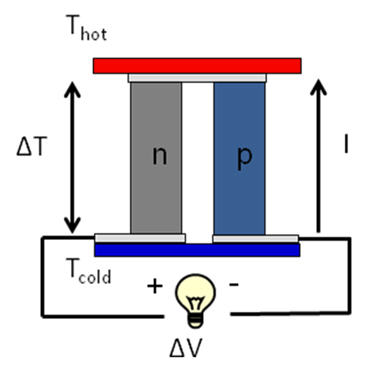
A thermoelectric converter (TEC) comprises p-type and n-type semiconductor legs sandwiched between two ceramic hot/cold plates and connected thermally in parallel and electrically in series as depicted in Fig. 1. The temperature gradient across the legs induces a voltage difference due to the Seebeck effect. The TEC performance is characterized by its figure-of-merit, ZT=S2T/(ρκ), where S is the Seebeck coefficient, ρ is the electrical resistivity and κ is the thermal conductivity. Due to the relatively low heat-to-electricity conversion efficiencies approaching 5% for ZT = 1, TECs have been mainly used in space applications. With the advent of novel functional ceramic materials, new high-temperature application areas are being considered, e.g. solar electricity generation. The new approach is to drive the TEC modules/arrays with concentrated solar radiation to obtain large temperature differences ΔT across the plates and, consequently, increases the energy conversion efficiency.
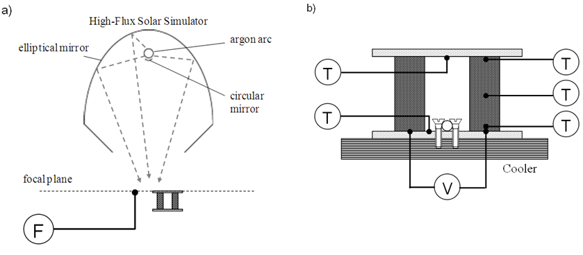
A FV-based heat transfer model of a TEC module is developed for simulating its thermal performance and analyzing the effect of the geometrical parameters. Coupled radiation/conduction/convection heat transfer with electrical potential distribution is considered for a TEC module directly exposed to concentrated solar radiation. The model is experimentally validated with measurements of temperature and voltages/power using a set of simplified 4-leg TEC modules that were directly irradiated. Figure 2 depicts the experimental setup at ETH's High Flux Solar Simulator.
Main research topics:
- Characterization of the radiation properties of the TEC components
- Heat transfer analysis and geometrical optimization of a single TEC module
- Design of a solar cavity-receiver packed with an array of TEC modules ("stack")
- Optimization for maximum solar-to-electricity energy conversion efficiency
- Conversion of waste heat, with focus on geothermal and solar waste heat
Project-related Publications